Imagine you're about to time block 2 events for tomorrow.
One takes 120 minutes, the other 75. You want to know exactly how much time it takes, you take your phone, use the calculator app, and add up 120 + 75.
In binary that’s 01111000 + 01001011.
At the end of this blog you’ll have a deeper understanding of how computers, and even your phone think, to make bit-by-bit calculations in addition.
If you’re not familiar with binary check out binary-part-0 where we dive into the basics of binary.
The 5 Parts Used in Binary Addition
You have input A, input B, and Carry In to calculate the total result. Carry In is the overflow from the previous bit-by-bit calculation.
Then you have sum and carry out both using logic gates. Sum represents the result bit, and Carry out communicates if there’s overflow.
Sum uses the XOR gate twice.
Carry Out uses AND, OR, and XOR.
How XOR is created
XOR is created by making use of all three basic gates; AND, NOT, and OR. In figure 1.0 below I show you an example of the XOR logic gate using a diagram:
This XOR circuit follows the logical expression: ((a AND NOT b) OR (b AND NOT a)).
Which is the definition of XOR: a is true if b is false, and b is true if a is false, if a is true and b is true then the output is false. Same in, if a is false and b is false then the output is false.
Next, let’s explore how the Sum logic works.
How Sum works under the hood
Sum looks a bit more complex under the hood, but its only difference is that it uses the XOR gate twice, as shown in figure 1.1.
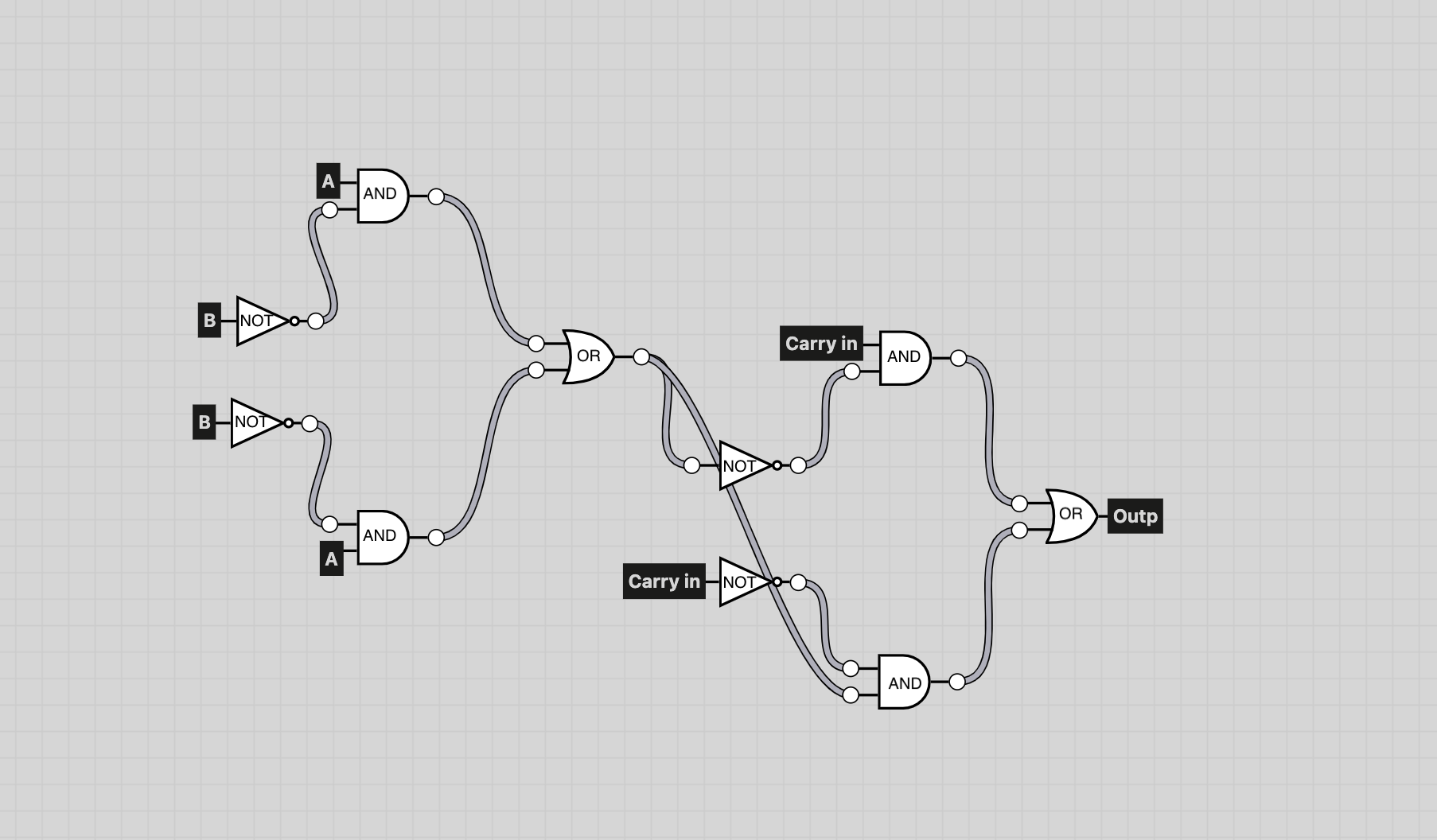
This Sum circuit follows the logical expression: (a AND NOT b) OR (b AND NOT a) = Output, then (CarryIn AND NOT output) OR (NOT output AND CarryIn).
So simply put, the Sum circuit follows 2X the logical expression: ((a XOR b) XOR carry in).
When the output of Sum is received it’s stored in memory.
Now, let’s move to the last layer of the full adder.
Carry out the last layer
Carry out is used to detect overflow, if there’s overflow then there’s no storage left in memory to point to.
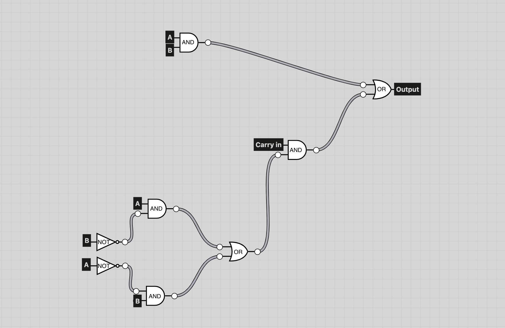
Carry out uses 3 gates: AND, OR, and XOR, in figure 1.2 below, I illustrate carry out using all three gates:
This Carry Out circuit follows the logical expressions: ((a AND b) OR (CarryIn AND (a AND NOT b) OR (b AND NOT a))).
Simply put Carry out in logical expressions: ((a AND b) OR (CarryIn AND (a XOR b))).
As you’ve seen in the three diagrams above, everything can be built using just three basic gates: AND, NOT and OR.
But, why are logic gates used?
Why logic gates are used
In addition the CPU in your PC communicates through logic gates. A CPU contains transistors which are the starting point before each logic gate, when enough voltage is received at the transistor it communicates ON, if no voltage is received, OFF. Then it goes through the logic gate, depending on each gate logic is applied.
Let’s look at an 8-bit full adder below using; Input_a, Input_b, Carry_in, Sum and Carry_out.
Each row follows a bit-by-bit calculation, starting from least significant bit (LSB) on the right hand side (bit_0 in the 8-bit full adder) to the most significant bit (MSB) on the left hand side (bit_7 in the 8-bit full adder).
Note:
Because computers start counting at Index 0 we will do the same, Bit_0 represents the Least Significant Bit (rightmost) bit in the byte, the one displayed at the top of the full adder.
And the Most Significant Bit (leftmost), is displayed at the bottom at Bit_7 of the full adder.
In decimal, the total range would be eight bits.
Carry_in is the Carry_out from the previous bit-by-bit calculation. So each Carry_in is carried from the previous row, and received from Carry_out.
You can read the remaining byte in the Sum column; a return value is given by repeating a bit-by-bit addition process 8 times.
Why This Matters for CPUs
Carry_in is the overflow of the previous bit-by-bit calculation. Once we Carry_in we know that the previous Carry_out had 1 bit that it couldn’t store, called overflow.
If at the end of the 8-Bit Full Adder, we end up with one bit overflow, then, the result may not fit in 8 bits, requiring more memory.
This means that the program may not compile for the user if memory doesn’t allow, else the CPU adds another byte if memory allows.
The Sum tells the CPU which value to store in memory, after the 8-bit full adder completes.
After pressing (=) on your calculation app the CPU follows this 8-Bit full adder and decimal number 195 is shown.
And just like that, you’ve seen how your phone adds 120 + 75, one bit at a time.
Closure
This is part I of a multi-part series exploring how binary logic powers real computing. I’m sharing what I learn as I go, from carrying logic to CPUs and memory.
Part II, covers subtraction and borrow logic.
If you want to stay updated follow me on: LinkedIn or, X/Twitter here I’ll post when part II goes live.
If you want to see programmed examples where I simulate logic gates using Rust, then check out: binarySeries
P.S. I used ChatGPT to fact-check, but ChatGPT and I can both make mistakes. If you spot a mistake, or see an opportunity to improve, feel free to reach out: Luuk@lukefi.com